|
How to Install the OMC Cobra Outdrive
Sterndrive installation, break in and oil fill instructions
|
- OMC Cobra installation instructions for upper to lower unit assembly
- Step by step details with diagram
and drawing
- Filling the outdrive with oil
- Break in period for new gears
- Testing water flow through
the case
|
|
OMC installation
|
|
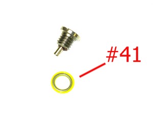
Sterndrive drain screw P/N 21731
|
|
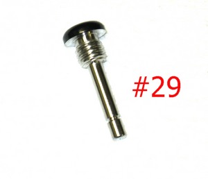
Cobra outdrive oil fill dipstick P/N 21732
|
|
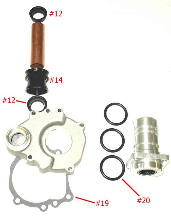
Please refer to the above diagram to identify the parts discussed below
|
|
How to install the lower unit onto the upper gearcase
When connecting the upper and lower unit together, pay special attention to the copper water pump tube (part #13) that
sits between the upper and lower sections.
You’ll notice there are 2 seals (part #12) –
one seal for the top of the tube, and one seal for the bottom of the tube where it sits in the water passage housing. Make
sure the water pump tube is aligned properly, and use Loctite sealing compound on the top seal. For the bottom seal, use a
gasket sealing compound where it fits into the water passage housing. Where the copper water pump tube seats into the plastic guide (part
#14), put a small amount of grease on the end of the tube. For the lower unit, the 3 o-rings (part #20) that fit
onto the bearing housing – make sure to use gasket sealing compound on only the bottom o-ring. Also, unit,
the gasket (part #19) that is under the water passage housing – make sure this gasket has sealing compound on this gasket.
If not, it is advisable to remove the water passage housing and apply gasket compound onto this gasket.
All the
seals outlined in the above steps are available on our lower unit parts drawing page
|
|
How to Fill the OMC Cobra with Oil
Start by locating the 2 drain screws in the lower unit (part #41A and #41B). Remove both screws.
*Note, when
re-inserting the drain screws, it is recommended to use new drain screw gaskets and apply some grease or gasket compound onto
the gaskets.
Insert one end your pump into the quart of lower unit oil, and then screw the other end where the
fitting is into the very bottom drain screw hole near the fin (part #41B), and begin pumping oil into the unit until it just
starts to come out of the upper drain screw (part #41A).
When it just starts to come out of the upper drain screw
(part #41A), remove the pump from the lower drain plug and re-insert the drain screw and new gasket. Use some grease or gasket
compound on the drain screw gasket.
Next, insert your pump into the upper drain screw hole (part #41A) and continue
filling the outdrive with oil until it reaches the very top dipstick (part #51). Re-insert the drain screw into the drain
hole (part #41A) and apply some grease onto the screw’s gasket.
*After running the sterndrive for 2 –
3 minutes at idle speed, allow 10 – 20 minutes for oil to settle, then re-check the oil level with the dipstick.
|
|
Testing Water Flow without Muffs
Please note: Do NOT only use muffs and a water hose to test the outdrive for proper water circulation. The water hose
has enough pressure to force water through the cooling system even if there is a problem at certain points in the path of
cooling system. ONLY in-water testing described below can accurately tell you if water flow will be adequate for cooling.
With the boat in the water, disconnect the hose from the thermostat housing. Testing should be done at idle speed, approximately
550 – 600 rpm.
In 1 – 2 minutes, you should be able to fill a bucket with 2 gallons of water. The
time to fill the bucket is based on engine size and recommended RPM. Please consult the OMC service manual for exact times
based on your engine.
Our primary concern is that there is a steady flow of water, no exhaust gasses pulsing and
no exhaust gasses in the water.
Note: Water pump pressure from the impeller is approximately 10 – 15lbs.
An exhaust manifold leaking into the water port area can reach approximately 40-60lbs – this can easily overtake the
water pump pressure and melt the impeller and impeller housing in the sterndrive.
Manifold leaks are commonly
caused by trapped or leftover water in the exhaust manifold over the winter in colder climates, or if it is not winterized
properly. Corrosion of the manifold can sometimes cause leaks, mainly in salt water areas.
|
|
Break In Period for New OMC Gears
- Avoid full throttle starts
- DO NOT operate at constant speeds for extended periods
- DO NOT exceed
75% of full throttle during the first 5 hours of operation
- During the next 5 hours, full throttle operation is permissible
for brief periods.
- Shift into forward gear a minimum of 10 times during break-in, with moderate engine speed after
each shift.
|
|